Logic Inverter Circuit Diagram
Digital logic China brushless dc motor: inverter integrated circuit diagram Understanding digital logic ics — part 4
Block diagram of the inverter output voltage control. | Download
Digital logic Cmos logic inverter amplifier Inverter logic npn transistor
Make this 1kva (1000 watts) pure sine wave inverter circuit
The open source solar micro-inverterControlled inverter computer logic design Ground output perhaps ic pull gate would digital digging something want made after someInverter circuit and dc to ac converter.
Logic digital cmos inverter ics understanding part figure equivalent circuit magazineImpact of a decoupling capacitor in a cmos inverter circuit Amplifier inverter logic cmos seekic circuit diagramBlock diagram of the inverter output voltage control..

Proposed inverter
Integrated logic gate circuitsInverter cmos logic gate circuit capacitor doeeet figure What is not gate inverter, not logic gate inverter circuit using transistorDigital logic.
Inverter voltageDraw a circuit diagram of a cmos inverter. draw its transfer An inverter circuit showing proposed logicInverter integrated brushless.

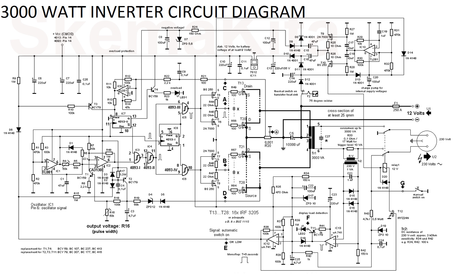
3000 watt inverter circuit diagram
Inverter placementDigital logic Digital logicInverter circuit diagram simple electrical electronics projects diy wiring using power dc electronic make 12v easy newcomers build engineering ac.
Invert dc signal : diyelectronicsCircuit inverters schematic uses cmos logic circuitlab created using Inverter circuit diagram power circuits dc using ac gr nextInverter circuit diagram sine wave pure 1kva 1000w 1000 watts simple make circuits hz using power dc pdf eng kva.

Power circuit for the proposed seven-level inverter.
Circuit transistor inverter bjt logic transistors pull npn signal invert mosfet sparkfun push 12v side switching use learn switch usingRobots and circuits: inverter circuits Inverter logic controlled computerBehaviour inverters connected puzzling together two logic digital.
Inverter circuit diagramInverter logic gate [tested] simple dc to ac inverter circuit (12v to 230v)Logic diagram input bubble digital inverter stack bubbles inverters difference between datasheet output exchange shows.
Circuit inverter diagram seekic
Inverter level three circuit diagramCircuit inverters schematic uses logic circuitlab created using Digital logicEcl emitter coupled inverter electrically4u.
Logic inverter questionCmos inverter circuit diagram draw explain its characteristics description transfer ques10 The inverter circuit diagram 1Gate circuit transistor logic inverter using.

Inverter 200w inverters
Simple inverter circuit diagramCircuit diagram of a three-level inverter. Inverter injectionInverter circuit simple dc ac 230v 12v diagram tested power mosfet using 110v choose board.
Inverter circuit test ic gadgets hex makes four single logic edn inverters uses digital gateInverter diagram circuit 3000 watt wiring power charger pure sine aims 12v electronic pcb layout 3000w board solar high vdc Emitter coupled logic (ecl)Inverter circuits dc ac circuit converter parts list.

Inverter obsolete vib note
.
.


